atmos:535:projects:sr50_sonic_ranging_sensor
Table of Contents
SR50 Sonic Ranging Sensor
- Manafacturer: Campbell Scientific, Inc.
- Model Number: SR50
— Randy Johnson 2008/12/11 11:46
Description
Cost
Initial Cost:
- Instrument: ~$1000
- Data Logger: ~$400
- Cable: ~$0.58/foot
Maintenance:
- The maintenance on the SR50 Sonic Ranging Sensor should be minimal. The silica gel desiccant packets, which are housed inside the instrument are recommened to be changed about once a year. Silica gel desiccant is approximately $0.10 per ounce. For more information, the following websites are recommended: http://www.google.com/search?hl=en&q=desiccant+packets&aq=f&oq=.
- The silica gel desiccant is used insure a dry environment for the electronics and the electrostatic transducer inside the SR50 Sonic Ranging Sensor. Moisture could affect the performance of these components.
Measurement Physics
Purpose:
- The SR50 Sonic Ranging Sensor is a device that is used to measure distance by using ultrasonic sound waves. Its primary applications are for measuring snow depth and water levels. The entire instrument is based on a 50 kHz electrostatic transducer.
Production of Ultrasonic Sound:
- An electrostatic transducer is a device that is capable of converting electrical signals into ultrasonic sound waves. It is also capable of taking ultrasonic sound waves and converting them into an electrical signal. The device accomplishes these tasks by taking advantage of the basic principles of electromagnetic theory that are involved with an electric field between two parallel conducting plates.
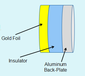
- The image located above reperesents the construction of an electrostatic transducer. The right side of the device is an aluminum plate. This plate is fixed so that it will always remain stationary. The left side of the device is a gold plate (thin, like a foil of gold). This plate is not held stationary like the aluminum plate so that it is free to move around. In between the gold and aluminum plates there exists an insulator (dielectric) material. This material is compressible and is often composed of Kapton. It is interesting to note that this construction is practically identical to that of a parallel-plate capacitor. Indeed, capacitance plays an important role in the operation of this device.
- The gold foil and the aluminum plate are connected to a 50 kHz signal generator. This generator initially applies a positive voltage to the gold foil and a negative voltage to the aluminum plate. A postive voltage implies a lack of electrons whereas a negative voltage implies the existence of an abundant amount of electrons. Because electrons have a negative charge this means that the signal generator intially causes the gold foil to be positively charged and the aluminum plate to be negatively charged. Consequently, an electric field between these parallel plates is produced.
- The electric field that is formed between the two parallel plates causes an attractive force between these plates. This stems from the basic fact of electromagnetic theory that electric fields are associated with a force in the presence of charged particles (in this case the gold foil and the aluminum plate). For a discussion on the strength of this attractive force the following discussion at the physicsforum is recommended: http://www.physicsforums.com/showthread.php?t=169113.
- Now that an attractive force has been established between the gold foil plate and the aluminum plate the two plates want to physically move closer to one another. Because the aluminum plate is always held stationary, the only way for this to happen is for the gold foil to move toward the aluminum plate compressing the Kapton dielectric in the process.
- Because the electrostatic transducer is being driven by a 50 kHz signal generator which produces a sinsusoidal signal in time, there comes a point at which no voltage is applied to either the gold foil or the aluminum plate. At this point there is no built up charge in either plate and thus no electric field causing the plates to move together. However, the restoring force associated with the Kapton dielectric material causes the Kapton to return to its original width before it was compressed by the movement of the gold foil. This pushes the gold foil plate away from the aluminum plate.
- Next, the 50 kHz signal applies a positive voltage to the aluminum plate and a negative voltage to the gold foil plate. This is opposite from the situation we started with. The result of this is that the electric field between these plates is reestablished and the gold foil plate compresses the Kapton dielectric in order to move closer to the aluuminum plate.
- It is easy to see that the gold foil plate is constantly moving toward and away from the aluminum plate. This movement causes a displacement of air. This displacement of air is the cause of ultrasonic sound waves. Thus, the electrostatic transducer produces ultrasonic sound.
Detection of Ultrasonic Sound:
- The electrostatic transducer is also capable of detecting ultrasonic sound. When an ultrasonic sound wave enters the electrostatic transducer, the wave (which is simply a perturbation in pressure) hits the gold foil. The extra air pressure associated with this wave causes the gold foil to move toward the aluminum plate compressing the Kapton dielectric in the process. It is a well known fact from electromagnetism that q = C x V, where q is equal to the charge, C is the capacitance, and V is the voltage difference between the two plates. The charge on the plates remains the same when the transducer is in its sound detection mode, so q remains constant. However, the capacitance, C, will increase when the distance between the plates decreases. Thus, when the sound wave hit the gold foil, the capacitance increases because the distance between the plates decreases. The voltage has to decrease because the charge on the plates remains the same. This change in voltage creates an electrical signal allowing one to know when the electrostatic transducer detects sound.
Measuring Distance with Sound:
- The electrostatic transducer can both produce sound waves and detect them. The SR50 Sonic Ranging Sensor takes advantage of that fact to use the electrostatic transducer to measure distance. At time t = 0 the Sonic Ranging Sensor induces the electrostatic transducer to create a sound wave. The sound wave travels from the sensor to its target at which point the wave bounces off the target and is sent back to the sensor. Then, at time t = t, the electrostatic transducer detects the reflected sound wave (the echo).
- Using this time the Sonic Ranging Sensor calculates a round trip distance by using the simple fact the distance = rate x time. The rate in this equation is simply the speed of sound in air. Dividing the round trip distance by two allows the Sonic Ranging Sensor to deliver the distance to the target.
- One important thing to note is that the speed of sound in air is dependent upon the temperature of the air. For this reason the SR50 Sonic Ranging Sensor needs an independent temperature reading. By default, the raw distance delivered by the SR50 Sonic Ranging Sensor is calculated for an air temperature of 0o Celsius. The independent temperature measurement is applied to the raw distance value to adjust for the actual speed of sound given the actual temperature. The equation for doing this is shown below.
Measuring Snow Depth
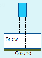
- To effectively measure the snow depth two measurements must be taken. The first is the distance from the SR50 Sonic Ranging Sensor to the ground. This value is assumed to be constant all winter, so it is important that the sensor does not move and is properly installed.
- The second distance that must be measured is the distance from the sensor to the top of the snow. Subtracting the distance to the snow from the distance to the ground yields the snow depth.
Performance Characteristics
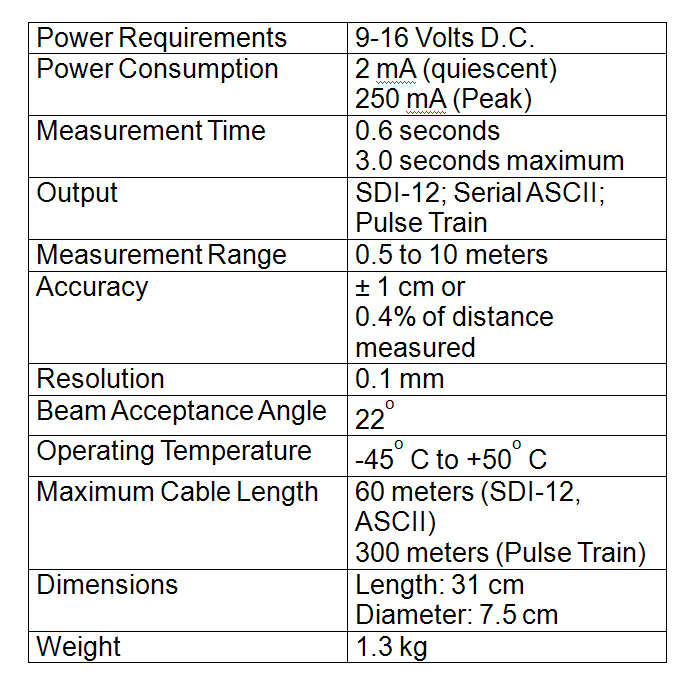
- The performance characteristics listed above were taken from the SR50 Sonic Ranging Sensor Instruction Manual produced by Campbell Scientific, Inc. To download the instruction manual and to find more information about the Sonic Ranging Sensor from Campbell Scientific the following website will prove helpful: http://www.campbellsci.com/sr50.
Field projects
- The SR50 Sonic Ranging Sensor is being used or has been used at many field sites.
- One such field site is the Surface Transportation Weather Research Center's field site at the University of North Dakota on Interstate 29: http://stwrc.rwic.und.edu/.
- This field site has four SR50 Sonic Ranging Sensors.
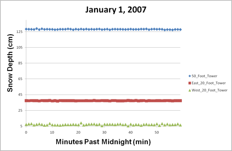
- Below is data taken from three of those sensors on January 1, 2007 from 12:00:00 AM to 12:59:00 AM.
- The measurements shown were taken once a minute for one hour.
- These data indicate that there was a large variation in the snow depth over the area of interest. One reason why the 50_Foot_Tower sensor showed such a high snow depth is because that sensor was located near a fence.
- The other thing to consider is that perhaps the sensors were not calibrated correctly. An independent measurement would have needed to be taken in order to check that.
- The table below shows the average snow depth for each sensor during this time period and the standard deviation for each sensor.
- One can see that the standard deviations are all under 1 cm. This is a good sign because the accuracy of this instrument is supposed to be within 1 cm or 0.4% of the distance measured (whichever is greater).
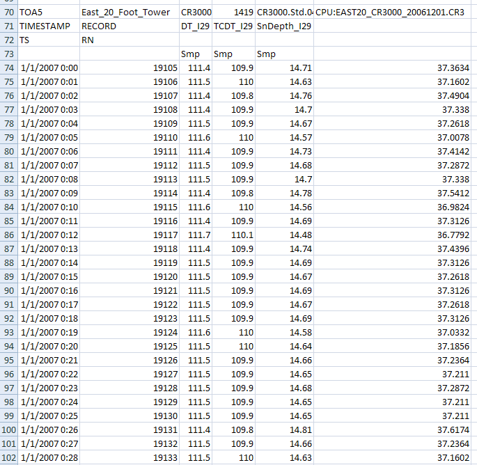
- Below is an example of what the data looks like when it comes in from the SR50 and the data logger and has been transferred to an Excel file.
Documentation
- SR50 Sonic Ranging Sensor Instruction Manual from Campbell Scientific, Inc. www.campbellsci.com/documents/manuals/sr50.pdf
- Surface Transportation Weather Research Center (STWRC) Buxton Field Site Snow Depth Data for SR50 January 2007.
Reference
- Campbell Scientific, Inc. http://www.campbellsci.com
- SensComp:
- PhysicsForums: http://www.physicsforums.com/showthread.php?t=169113
- Dr. Matt Nolan, University of Alaska Fairbanks: http://www.polarpower.org/examples/mccall_glacier_weather_stations/index.html
- Jennifer Hershey, STWRC Field Site Manager
- Special Thanks:
- Jennifer Hershey
Calibration
Method
- The SR50 Sonic Ranging Sensor can measure distances between 0.5 meters and 10 meters. The instrument must be calibrated over this range so that one can insure accurate data. In order to calibrate the instrument, independent measurements of the distances over the range being measured needs to be obtained for comparison with the sensor data.
- The SR50 Sonic Ranging Sensor also relies on an independent temperature reading. The instrument being used to measure the temperature must also be calibrated over the range of temperatures to which the SR50 will be exposed. If the temperature instrument is not calibrated, the error in temperature will translate into an error in the distance measured by the SR50.
Sources of Error
- There are several ways in which error can be introduced into the measurements taken by the SR50 Sonic Ranging Sensor:
- Error in the Independent Temperature Reading
- Tilted Instrument
- Obstructed View
- Uneven Target Surface
- Small Target
- Poor Sound Reflectors
Calibration Checked
- In order to check the calibration, independent measurements must be taken for comparison with the results of the SR50. These indepedent measurements must represent the range of distance that the SR50 can measure and must be taken over the range of temperature in which the SR50 can operate.
Exposure Requirements
- The SR50 Sonic Ranging Sensor was built to endure harsh environments. That does not mean, however, that the SR50 does not have its limits.
- The sensor was designed to operate from -45o to 50 Celsius (-49o to 122o Fahrenheit).
- If one is measuring snow depth, one should take into account effects such as snow drift. In order to get an accurate reflection of the true snow depth, multiple sensors is desirable. Multiple sensors would allow one to know weather or not the snow depth is level or uneven over the area of interest.
- Obstructive Objects must also be taken into account:
- Fences will gather more snow near them because of the wind. Placing a sensor near a fence will result in higher than normal snow depths.
- Trees will prevent the accumulation of snow from underneath their branches. Placing a sensor under a tree will likely result in smaller snow depths than in an open area sheltered from the wind.
- The SR50 Sonic Ranging Sensor must also be supported by good, strong, stable supports. If the instrument is not stably supported then the movement of the SR50 in the wind could result in inaccurate measurements.
Deployment
Measurement Methods
Deployment Platforms
- The SR50 Sonic Ranging Sensor can be deployed in many different platforms. It is ideal for measuring distances, especially distances that may have a tendency to change with time.
- The SR50 could be used to detect a change in water levels. For instance, it could be used to check the water level in lakes and streams for drought monitoring purposes.
- The SR50 is also used to measure snow depths for surface transportation research. For more information on this visit the website of the Surface Transportation Weather Research Center at the University of North Dakota. http://stwrc.rwic.und.edu/
- The SR50 is even used in the study of glaciers. For more information on this visit the website of Dr. Matt Nolan at the University of Alaska Fairbanks. http://www.polarpower.org/examples/mccall_glacier_weather_stations/index.html
Communication
- Communication with the SR50 Sonic Ranging Sensor is vital. In order for a computer to communicate with the SR50 a data logger is needed. The following models should be compatible with the SR50 Sonic Ranging Sensor and are available from Campbell Scientific, Inc.:
- CR10(X)
- CR500
- CR510
- CR23(X)
- BDR320
- CR200
- Data loggers are responsible for retrieving the data from the Sonic Ranging Sensor and delivering the information to a personal computer.
Power and Installation
- Requires 9-16 volts D.C.
- Consumes 2mA (quiescent) or 250mA (peak).
- Must have a clear cone radius. The cone radius describes the area under the SR50 where the instrument listens for an echo. If there are any unwanted objects in this zone then the distance delivered by the SR50 could be the distance to that object instead of the distance to the target. The cone radius is equal to 0.194 mulitplied by the distance from the SR50 to the target. The reason for the factor of 0.194 is because the total beam acceptance angle of the SR50 is 22 degrees and the tangent of 11 degrees is 0.194.
- The SR50 Sonic Ranging Sensor must also be properly mounted. A good mounting job will leave the instrument perpindicular to the surface or target. Examples of proper mounting can be found in the SR50 Sonic Ranging Sensor Instruction Manual available from Campbell Scientific, Inc. www.campbellsci.com/documents/manuals/sr50.pdf
System Automation
- The SR50 can be programmed to take data automatically. For instance, the SR50 can take a measurement once a minute or once an hour if that is desired.
Data
Quality Control
- The SR50 Sonic Ranging Sensor has several quality control measures:
- If the distance to the target is moving by more than 4 cm/sec then the reading is rejected (another important reason to make sure the instrument is stably supported).
- If the SR50 fails to detect an echo then a 0 is returned for the distance.
Quality Assurance
- There is an option for the data to return with quality numbers. These numbers range from 162 to 600.
- 162 - 210: Means the target was well defined.
- 210-300: Means the target was not clearly defined.
- 300 - 600: Means the target was of poor quality.
- High numbers can be caused by little sound reflection or an uneven target surface.
atmos/535/projects/sr50_sonic_ranging_sensor.txt · Last modified: 2020/01/29 17:25 by 127.0.0.1
