Table of Contents
Intelligent Road Sensor
Description
Measurement Physics
Summary of Measurements
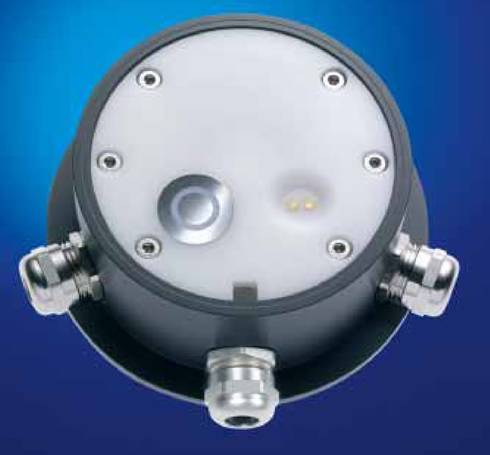
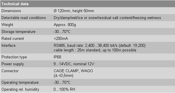
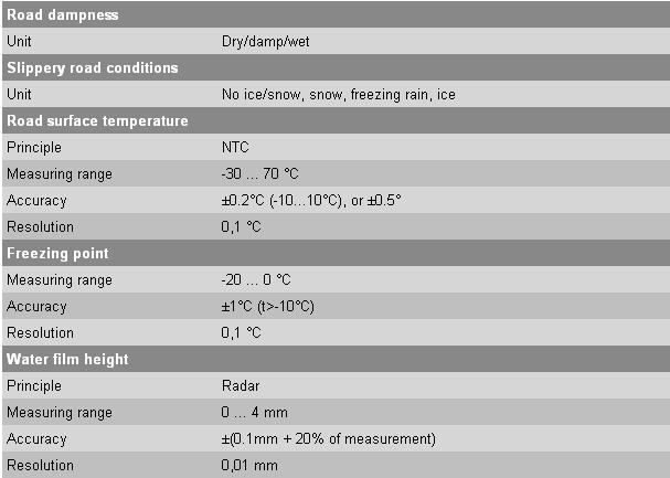
The Lufft Intelligent Road Sensor measures surface pavement temperature, salt concentration, water film height, multi-frequency and has the option of measuring temperature at two different locations (typically below pavement and in pavement). These measurements are then sent back to a data logger through a communication cable where the freezing temperature and pavement condition can be predicted based off of data collected from the Intelligent Road Sensor.
Temperature
- Temperature sensor is located inside the dent of the Intelligent Road Sensor in the central electrode.
- Temparature sensor is a thermistor in which the resistance of the thermistor is a function of temperature.
- This sensor measures the surface pavement temperature, which is needed to know if ice is possible to form on the pavement.
- If the two optional temperature probes are added they can measure subsurface temperatures.
- Measured in degrees Celcius
Salt Concentration
- Measured with the two electrodes inside the dent of the Intelligent Road Sensor.
- As more current can pass between the two electrodes the higher the salt concentration is on the road.
- Uses electrodes designed specifically for salt measurement
- Measurements are in % salt concentration
- Only salt is measured, but other chemicals can be requested to be integrated in by manufacturer
Freezing Temperature
Water Film Height
- Water film height is measured with a CW-radar (continious-wave radar) located inside the Intelligent Road Sensor
- A continious wave radar is a radar who continously sends out a wave and recieves a signal back from it. This is unlike pulse radars that are commonly used in meteorology.
- A CW-radar normally can not measure distance but a frequency shift can be used to determine distance.
- Water film height can be measured up to 4mm.
- However, water film height is recorded as an index from zero to 250 in which 150 represents no water film on the Intelligent Road Sensor, readings closer to zero mean more water is on the sensor and readings closer to 250 mean more ice is on the sensor.
Multi-Frequency
- Is the two metal circles on the surface of the Intelligent Road Sensor.
- It is an impedance sensor
Road Conditions
- Not directly measured but instead based off of the readings from the Intelligent Road Sensor
- Processed inside the sensor
- Road can be in the following conditions and the numbers next to them represent the code recorded onto the data logger for road condition
- Dry (0)
- Damp (1)
- Wet (2)
- Ice (3)
- Frost / Snow (4)
- Residual Salt (5)
- Freezing Wet (6)
- Undefined / Can not be determined (98,99)
- A nominated temperature “TPOS” is used (default value 2ºC)
- If above road can be “Dry”, “Residual Salt”, “Damp”, and “Wet”
- If below the road can also be “Freezing Wetness”, “Frost / Snow” and “Ice”
-= Performance Characteristics =-
Field projects
The Intelligent Road Sensor is currently being used at the Surface Transportation Weather Research Center's (STWRC) field site located off of I-29 south between exit number 123 (Reynolds) and 118 (Buxton). More information on the STWRC's field site can be found here http://stwrc.rwic.und.edu/
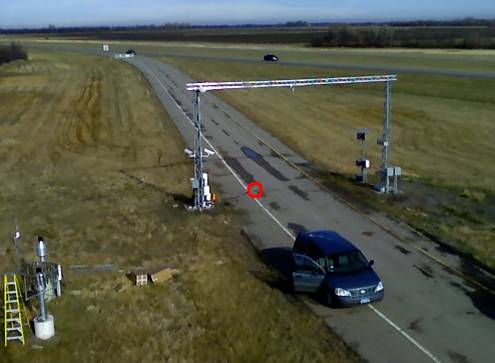
This is a picture of the field site where the Intelligent Road Sensor is circled in red
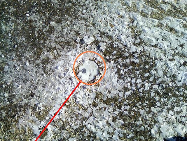
This is a close up picture of the Intelligent Road Sensor at the field site. The red line shows where the communication cable is that leads back to a data logger. The Orange circles shows that inside that and the actual Intelligent Road Sensor where there is a freely conducting insullation (in the picture it looks like rust colored moss).
Reference
- http://www.lufft.com/e_index.htm (Has a link to the manual there and shows the preformance characteristics)
- http://en.wikipedia.org/wiki/Continuous-wave_radar (Information on the CW-Radar)
- http://www.lufft.de/download/manual/IRS_20V1.29_e.pdf (Online Manual of the Intelligent Road Sensor)
- http://www.lufft.de/download/La/pavement_sensor_rpt.pdf (Used later for possible calibration tests)
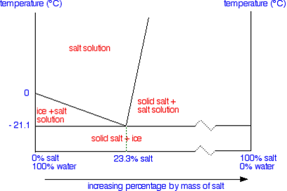
- http://www.chemguide.co.uk/physical/phaseeqia/saltsoln.html (For freezing temperature picture)
- http://www.traftech2000.com/lufft/Sens-to-Sign.pdf (For picture of sensor-to-sign and information about it)
Calibration
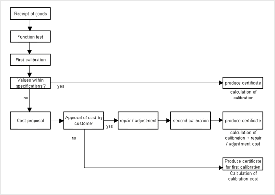
The Intelligent Road Sensor comes with a certificate stating the calibration test results. Calibration tests can be done either by Lufft (which takes time and money) or by doing verious tests. Below is a schematic that Lufft provides to show the cailbration process works.
Method
The Aurora project has run several different calibration tests on various pavement sensors, uncluding the Intelligent Road Sensor. The reason for the several different tests is that pavement sensors need to be able to give back accurate feedback under various conditions. The Intelligent Road Sensor needs to be able to give back accurate temperature readings and salt concentartion in order to be able to give back a reliable road condition. For these tests thermistors that were calibrated in an ice bath were used as the truth temperature to be compared to the pavement sensors surface temperature readings. These were the following tests done onto the Intelligent Road Sensor while put under field site conditions (ie the sensor was outside and installed into a road):
- Cold day with and without direct solar impact
- Cold night with and without strong radiational cooling
- Warm pavement with snowfall
- Cold pavement with rainfall
- Iced pavement with rainfall
Also some lab tests were done with checking the salt concetration measurements. This is important because how accurate the salt measruement is the more accurate the freezing temperature will be and in critical conditions the freezing temperature is very important to know if ice will form on the road or not. Using a known salt concentration that was sprayed onto the instruments the following tests were done:
- NaCl on a cold day with and without direct solar impact
- NaCl on warm pavement with snowfall
- NaCl on cold pavement with rainfall
- NaCl on iced pavement with rainfall
The results from these tests can be found at: http://www.lufft.de/download/La/pavement_sensor_rpt.pdf
Calibration Checked
It is recomended by the manufacturer to do a calibration tests once every year. If the unit needs to be removed it needs to be done on a non-preciptation day with dry pavement. The Itelligent Road Sensor can also be sent back to Lufft for calibrations or tests can be done on your own time and with your own resources. Calibration tests like the ones mentioned above have not been done onto the Intelligent Road Sensor at the STWRC field site.
Deployment / Usage
Exposure Requirements
The Intelligent Road Sensor was designed to be pavement for long periods of time. This sensor was designed to be outdoors and in extreme temperatures. It is suggest to be placed in right lane in the United States (this prevents from a lot of the pavement having to be destroyed for the communication cable and also places the sensor in a lane of higher traffic. However, if the sensor ever needs to be removed it has to be done on a day without precipitation and the pavement needs to be dry. Getting humidity into the sensor will result in malfucntions of the sensor. Also if the sensor is removed, the outer casing is still there and it is recommend to clean the casing before installing the sensor back into the pavement and to clean the sensor as well.
Communication
Communication to and from the Intelligent road sensor is done through the communication cable which is connected to a data logger. The STWRC field site uses a Cambell Scientific data logger, but a data logger designed by Lufft works as well.
Power
The Lufft runs off of a 12V power supply provided by the data logger. At the STWRC's field site there is the 12V power supply can be directly powered from an outlet or in case of power failure there is a battery back-up as well.
Installation
It is important to note that it is very important to keep the sensor flush with the road and to not have the sensor go above the road surface. If the sensor is above the pavement then the sensor can get dmaged when snow plows run over it or could damage the plow as well. An installtion aid is provided to help keep the sensor flush with the pavement. Also resine concrete was used to fill in the gap but the concrete can not reach temperatures above 80 degrees Celcius in the curing process, if this happens it is possible that the sensor can get damaged. The field site used a freely conducting insullater instead of the resine concrete.
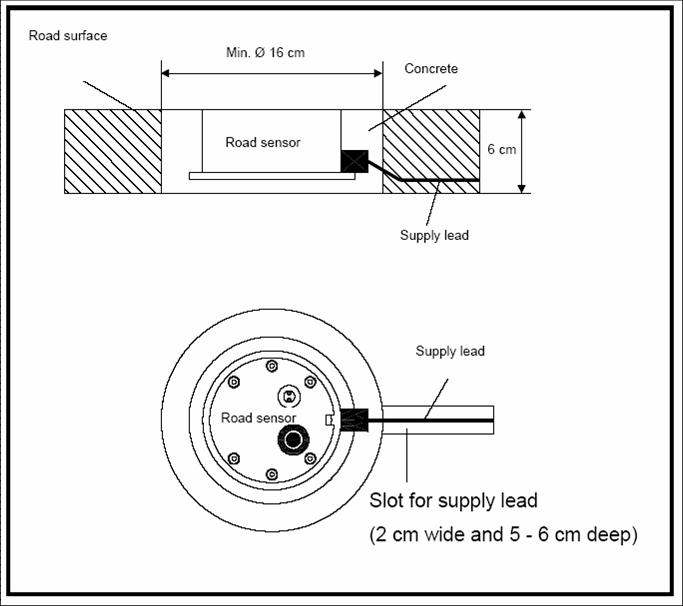
This is a diagram of the installed Intelligent Road Sensor
The main thing to point out with installation is that once the sensor is in the pavement it is pretty permanent. The inner part of the sensor can be removed but the outer part can not. Also in order to install these a lot of manual work and possible road closures are needed. In addition pavement needs to be removed for not only the sensor but the communication cable as well. This could lead to a problem if one is to install maybe a 100 of these sensors throughout the state. Furthermore, the location of the sensors need to be known so that road maintanence can be sure to not lay a chip coat on top of the sensors. If a chip coat or some form of sealent was layed on top of the sensors, the sensor can no longer be used and was just destroyed.
Who Could Use Intelligent Road Sensor Data
The main group of people who could use data collected from the Intelligent Road Sensor is the Department of Transportation. The Department of Transportation needs to be able to make decisions on winter road maintanence and could use data collected from a network of Intelligent Road Sensors to decided whether to de-ice or to salt or to just plow. Knowing the road conditions in a real-time scenario could help roads with a higher need of plowing or deicing get action done onto them faster because of the provided data as well. Also if adjustable speed limit signs are in place, then in adverse weather conditions, like ice, the speed could be lowered before an accident happens.
Also data from the Intelligent Road Sensor can be put into models that help predict road conditions and make plowing forescasts / plans as part of the model.
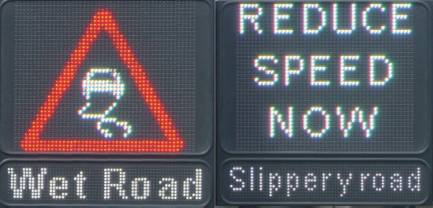
One idea that Lufft has for the Intelligent Road Sensor data is a LED sensor-to-sign that changes as the conditions on the road change. This information would be provided from an Intelligent Road Sensor and connected directly to the LED sign. If the road is icy and warning to slow down could be displayed, the same for a wet road ahead. This could be particullary useful for bridges because they freeze over before the actual road does.
Data
- A live feed of data collected from the Intelligent Road Sensor can be found at the following link http://stwrc.rwic.und.edu/fieldsite/live/
- Data from the Intelligent Road Sensor is being stored and archived for the purposes of research at STWRC and collected every 2 minutes as well as a 30 minute average.

This is data pulled from the data logger.
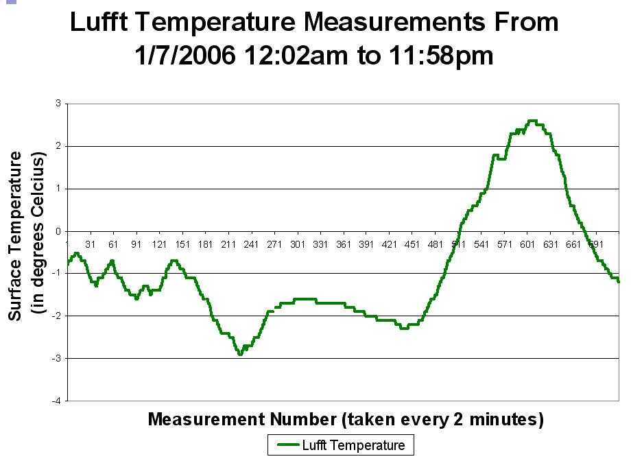
This is a graph of surface temperature data taken on January 7, 2006 from 12:02am to 11:58pm. Unfortunatly, due to the time stamp, the x-axis had to be masurement number instead of time.
